Mark Dominus (陶敏修)
mjd@pobox.com

Archive:
| 2026: | JFM |
| 2025: | JFMAMJ |
| JASOND | |
| 2024: | JFMAMJ |
| JASOND | |
| 2023: | JFMAMJ |
| JASOND | |
| 2022: | JFMAMJ |
| JASOND | |
| 2021: | JFMAMJ |
| JASOND | |
| 2020: | JFMAMJ |
| JASOND | |
| 2019: | JFMAMJ |
| JASOND | |
| 2018: | JFMAMJ |
| JASOND | |
| 2017: | JFMAMJ |
| JASOND | |
| 2016: | JFMAMJ |
| JASOND | |
| 2015: | JFMAMJ |
| JASOND | |
| 2014: | JFMAMJ |
| JASOND | |
| 2013: | JFMAMJ |
| JASOND | |
| 2012: | JFMAMJ |
| JASOND | |
| 2011: | JFMAMJ |
| JASOND | |
| 2010: | JFMAMJ |
| JASOND | |
| 2009: | JFMAMJ |
| JASOND | |
| 2008: | JFMAMJ |
| JASOND | |
| 2007: | JFMAMJ |
| JASOND | |
| 2006: | JFMAMJ |
| JASOND | |
| 2005: | OND |
Subtopics:
| Mathematics | 246 |
| Programming | 100 |
| Language | 95 |
| Miscellaneous | 75 |
| Book | 50 |
| Tech | 49 |
| Etymology | 36 |
| Haskell | 33 |
| Oops | 30 |
| Unix | 27 |
| Cosmic Call | 25 |
| Math SE | 25 |
| Law | 23 |
| Physics | 21 |
| Perl | 17 |
| Biology | 16 |
| Brain | 15 |
| Calendar | 15 |
| Food | 15 |


Comments disabled
Thu, 16 Nov 2006
Etch-a-Sketch blue-skying, corrected
In my last article I
discussed a scheme for improving the Etch-a-Sketch which contained a serious
mechanical error. I was discussing attaching gears to the two knobs
of the Etch-a-Sketch to force them to turn at the exact same rate. Supposing
that the distance between the knobs is 1 unit, I said, then we can
gear the two knobs together by attaching a gear of radius 1/2 to each
knob; the two gears will mesh, and the knobs will then turn at the same
rate, in opposite directions. This was fine.
Then I went astray, and suggested adding an axle peg midway between the two knobs, and putting gears of radius 1/3 on the peg and on the two knobs. This won't work.
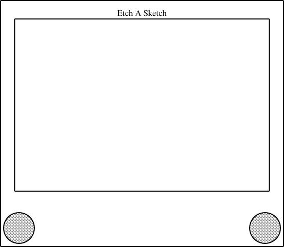
The one person who wrote to me to ask about the problem is a very bright person, but been seriously confused about how I was planning to set up the gears, so I evidently I didn't explain it very well. It needed a picture. So this time I'm going to try to get it right, with pictures. Here is an Etch-a-Sketch:
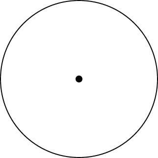
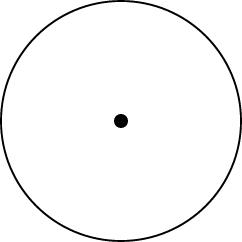
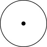
Here are some gears, which happen to have radii 1/3, 1/4, and 1/6:
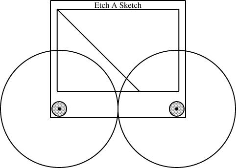
Here's a picture of an Etch-a-Sketch with a radius-1/2 gear mounted on each knob:
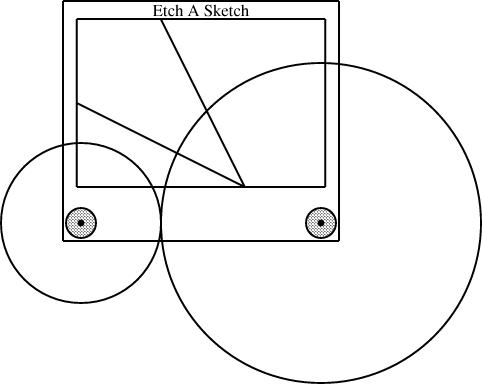
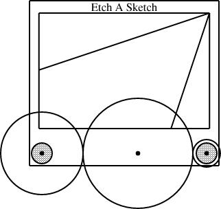
Here the knobs have been fitted with different-sized gears, one with radius 1/3 and the other with radius 2/3:
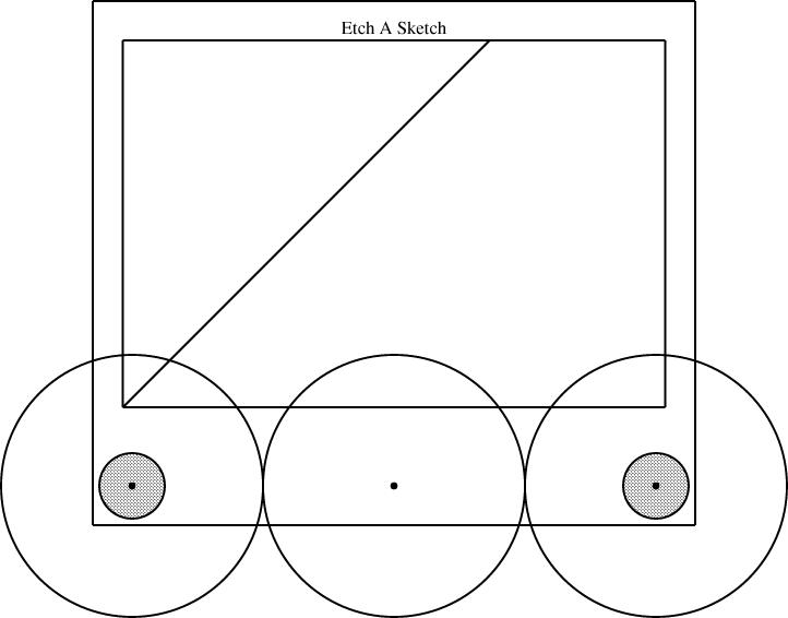
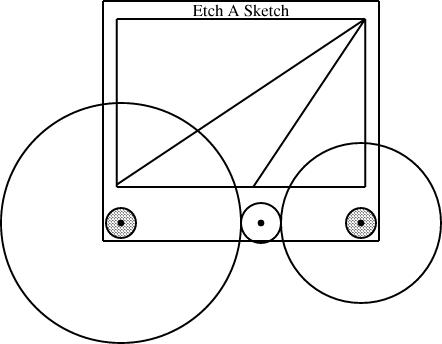
Then I suggested that you could drill a little hole in between the two knobs, and use it to mount a third axle and a third gear. If all three gears are the same size, the two knobs are forced to turn at the same rate, this time in the same direction, and you get a line with slope 1, from southeast to northwest:
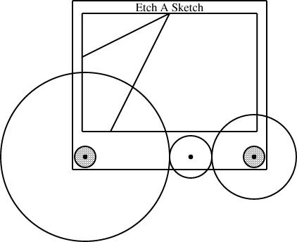
This wrecks the rest of the details of my other article. Since we were already including gears of size 1/2 and 1/3, I reasoned, we can throw in a gear of size 1/6 and get some new behaviors from the 1/2 + 1/3 + 1/6 combination. The corresponding combination for 1/2 and 1/4 is 1/8:
So what next? The calculations are a bit less obvious than they were back in the happy days when I thought that installing two gears of size p and q left space for one of size 1-(p+q). It's tempting to consider a radius-1/3 gear next, since it's the simplest size I haven't yet installed. But to mount it on the knobs along with a size-1/2 gear, we need to include a size-1/12 gear to go in between:
Once we have the size-1/12 gear, we can mount it with the size-1/4 and size-1/3 that we already had:
[Other articles in category /games] permanent link